DIGITAL ELECTRONICS
DIGITAL ELECTRONICS NOTES
1. 4-BIT PARALLEL ADDER
A 4-bit Parallel Adder is a combinational circuit used to add two 4-bit binary numbers. It consists of four Full Adders connected in cascade. Each Full Adder adds:
- One bit from input A
- One bit from input B
- Carry from the previous stage
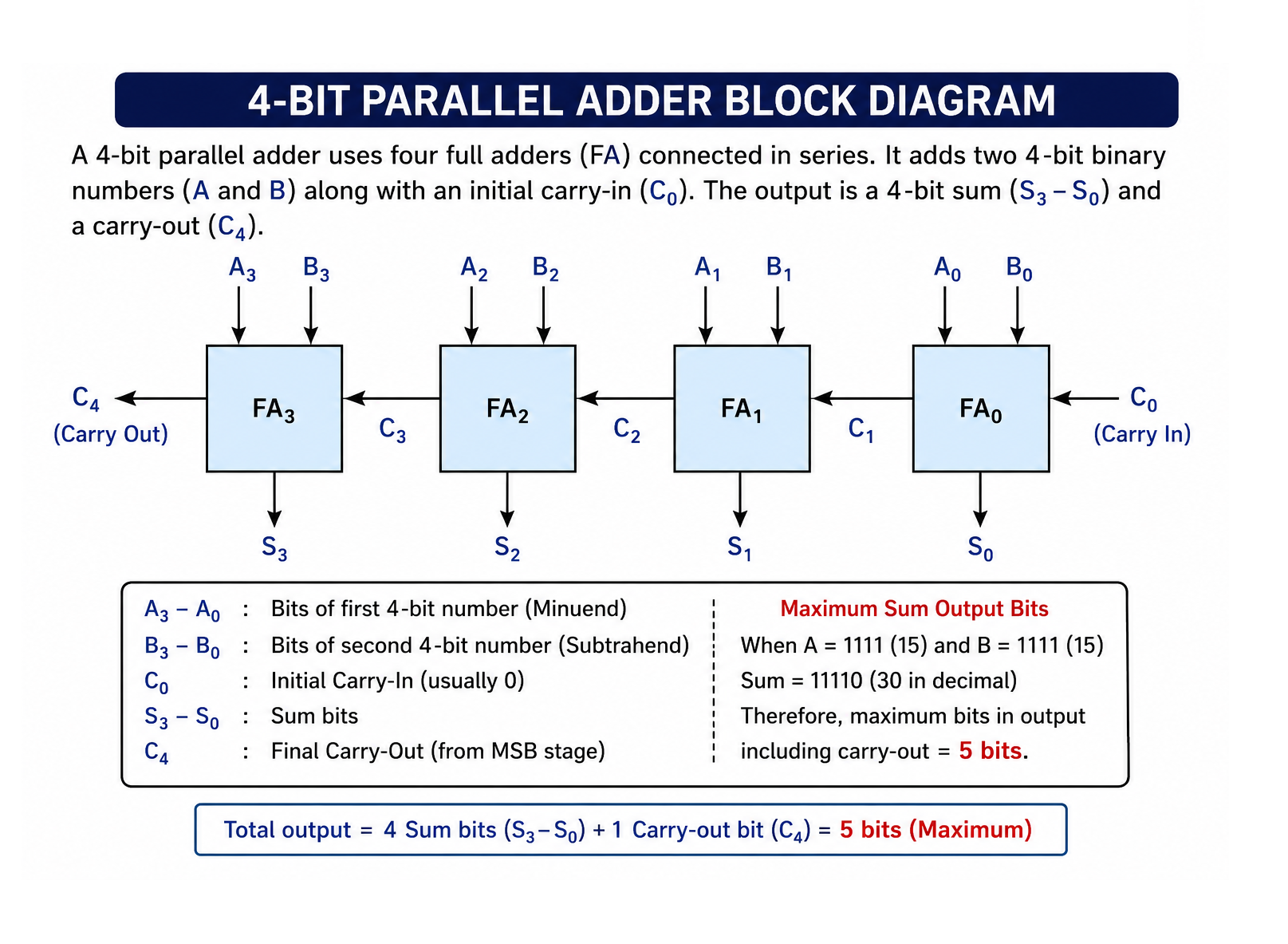 Block Representation
A3 B3      A2 B2      A1 B1      A0 B0
 |  |        |  |       |  |       |  |
+-----+    +-----+    +-----+    +-----+
| FA3 |<---| FA2 |<---| FA1 |<---| FA0 |
+-----+    +-----+    +-----+    +-----+
    |          |          |          |
   S3         S2         S1         S0

Carry Out = C4
Maximum Sum Output
Maximum 4-bit number:
1111₂ = 15₁₀Adding two maximum numbers:
1111
1111
-----
11110
Result:
- Sum Bits = 4
- Carry-Out Bit = 1
Therefore,Maximum number of bits in output = 5 bits
Example
A = 1111
B = 1111

Output = 11110Hence:Sum Output = S3 S2 S1 S0 + Carry-Out = 5 bits
2. MULTIPLEXER (MUX)
A Multiplexer (MUX) is a combinational circuit that selects one input from many inputs and transfers it to a single output.
Definition
Many-to-One Data Selector
Characteristics
- Multiple inputs
- One output
- Selection controlled by Select Lines
General Relation
For n Select Lines:
Number of Inputs = 2ⁿ4:1 Multiplexer
Inputs:
I0, I1, I2, I3Select Lines:
S1, S0Output Equation:
Y = I0S̅1S̅0 + I1S̅1S0 + I2S1S̅0 + I3S1S0Functions
- Data Routing
- Channel Selection
- Communication Systems
- Digital Switching
Example
For a 2:1 MUX:
I0 = 0
I1 = 1
S = 1
Output Equation:
Y = S̅I0 + SI1Substituting values:
Y = (0×0) + (1×1)
Y = 1
Output = 1
3. SHIFT REGISTERS
A Shift Register is a group of flip-flops used for storage and transfer of binary data.
SISO (Serial In Serial Out)
Characteristics
- Data enters serially.
- Data leaves serially.
Clock Requirement
For n bits:
- Input Loading = n clock pulses
- Serial Output = (n−1) clock pulses
SIPO (Serial In Parallel Out)
Characteristics
- Serial input
- Parallel output
Working
Each clock pulse shifts data by one stage.For an n-bit register:
- n clock pulses are required to load n bits.
- After loading, all outputs are available simultaneously.
Example
For a 4-bit SIPO:
Input Data = 1011

Clock 1 → 1
Clock 2 → 10
Clock 3 → 101
Clock 4 → 1011
After 4 pulses:
Q3 Q2 Q1 Q0 = 1011Parallel outputs can be read simultaneously.
PISO (Parallel In Serial Out)
Characteristics
- Parallel Loading
- Serial Output
Clock Requirement
- Parallel Loading = 1 clock pulse
- Serial Output = (n−1) clock pulses
PIPO (Parallel In Parallel Out)
Characteristics
- Parallel Input
- Parallel Output
Clock Requirement
| Operation | Clock Pulses |
|---|---|
| Input Loading | 1 |
| Output Reading | 0 |
Example
For a 4-bit PIPO Register:
Input = 1101After one clock pulse:
Output = 1101No additional clock pulse is required to read the output.
4. FULL SUBTRACTOR
A Full Subtractor subtracts:
A − B − Binwhere:
- A = Minuend
- B = Subtrahend
- Bin = Borrow Input
Outputs:
- Difference (D)
- Borrow Out (Bout)
Difference Equation
D = A ⊕ B ⊕ BinExample
A = 1
B = 0
Bin = 1
D = 1 ⊕ 0 ⊕ 1
D = 0Truth Table
| A | B | Bin | D | Bout |
|---|---|---|---|---|
| 0 | 0 | 0 | 0 | 0 |
| 0 | 0 | 1 | 1 | 1 |
| 0 | 1 | 0 | 1 | 1 |
| 0 | 1 | 1 | 0 | 1 |
| 1 | 0 | 0 | 1 | 0 |
| 1 | 0 | 1 | 0 | 0 |
| 1 | 1 | 0 | 0 | 0 |
| 1 | 1 | 1 | 1 | 1 |
5. RING COUNTER
A Ring Counter is a recirculating shift register.
Structure
Serial Output is connected back to Serial Input.
Q0 → Q1 → Q2 → Q3 → Q4
↑                 ↓
└─────────────────┘
States
For n Flip-Flops:
Number of States = nExample
5-bit Ring Counter:
States = 56. SERIAL BINARY ADDER
A Serial Adder performs addition one bit at a time.
Important Characteristic
Each Full Adder waits for the carry generated by the previous Full Adder.
Features
- Sequential operation
- Less hardware
- Slower than parallel adder
7. MEMORY ADDRESS LINES
Example
Memory Capacity:
4 KBConversion:
4 × 1024
= 4096 Bytes
Since:
4096 = 2¹²Required Address Lines:
n = 12Answer = 12 Address Lines
8. 2'S COMPLEMENT SUBTRACTION
Subtraction is performed as:
A + (2's Complement of B)Carry-Out Rule
If the result is positive:
Carry-Out Bit is IgnoredExample
9 - 5

1001
+1011   (2's complement of 5)
------
10100
Ignoring carry:
0100 = 49. T FLIP-FLOP
A T Flip-Flop toggles when:
T = 1Example
Initial:
Q = 0After Clock Pulses:
| Pulse | Q |
|---|---|
| Initial | 0 |
| 1st | 1 |
| 2nd | 0 |
| 3rd | 1 |
Final Output:
Q = 110. ASYNCHRONOUS (RIPPLE) COUNTER
Characteristic
Only the first flip-flop receives the external clock.Each subsequent flip-flop receives clock from the previous flip-flop output.
CLK → FF0 → FF1 → FF2 → FF3Important Point
Clock input of every flip-flop except the first is connected to:Output of Previous Flip-Flop
11. DECODER
A Decoder converts binary input into one active output line.
Characteristics
For n inputs:
Outputs = 2ⁿApplications
- Code Conversion
- Memory Address Decoding
- Display Systems
Example
BCD to Decimal Conversion
BCD Input
     ↓
 Decoder
     ↓
Decimal OutputTherefore:A circuit used to convert a BCD number into equivalent decimal form is called a Decoder.
12. COUNTERS
For n Flip-Flops:
Total States
2ⁿLargest Count
2ⁿ − 1MOD Counter Design
Condition:
2ⁿ ≥ MOD NumberExample: MOD-10 Counter
2⁴ = 16 ≥ 10Therefore:
Required Flip-Flops = 4Also called:
Divide-by-10 Counter13. JOHNSON COUNTER
A Johnson Counter is a modified Ring Counter.
Structure
Inverted output of last flip-flop is fed back to first flip-flop.
Q̅n → First Flip-Flop InputMOD Value
For n Flip-Flops:
MOD = 2nUnused States
Unused States = 2ⁿ − 2n14. RIPPLE COUNTER DELAY
For n-bit Ripple Counter:
Maximum Delay = n × tpdwhere:
tpd = Propagation Delay per Flip-FlopExample
n = 4
tpd = 25 ns
Delay = 4 × 25
= 100 nsImportant Note
For synchronous counter:
Delay = tpd of one Flip-Flop only15. COUNTER OUTPUTS
The parallel outputs of a counter represent:Clock Count
Example
For output:
1010₂Count Value:
10₁₀Thus, parallel outputs provide binary representation of the count.
16. TTL ICs
| IC Number | Function |
|---|---|
| 7400 | Quad 2-input NAND |
| 7402 | Quad 2-input NOR |
| 7404 | Hex NOT Gate |
| 7408 | Quad 2-input AND |
| 7411 | Triple 3-input AND |
17. BOOLEAN FUNCTIONS
For n Variables:
| Variables | Boolean Functions |
|---|---|
| 0 | 2 |
| 1 | 4 |
| 2 | 16 |
| 3 | 256 |
| 4 | 65536 |
Important Result
For 4 Variables:
Number of Boolean Functions = 6553618. MASTER-SLAVE JK FLIP-FLOP
A Master-Slave Flip-Flop consists of two cascaded flip-flops:
- Master Flip-Flop
- Slave Flip-Flop
Structure
Clock
  ↓
Master FF
  ↓
Slave FF
  ↓
Output
Operation
CLK = HIGH
- Master Active
- Slave Inactive
CLK = LOW
- Slave Active
- Master Inactive
Latest master output transfers to slave.
Important Features
- Eliminates Race Around Condition
- Output changes only once per clock pulse
- Similar to Negative Edge Triggered Flip-Flop
19. FLIP-FLOP
A Flip-Flop is the basic storage element of digital electronics.
Characteristics
- Stores 1 bit information
- Built using logic gates
- Fundamental building block of sequential circuits
Sequential Circuit
Output depends on:
- Present Input
- Previous State
Therefore:Basic building block of sequential logic circuit = Flip-Flop
20. FDM AND TDM
Frequency Division Multiplexing (FDM)
Characteristics
- Used for Analog Transmission
- Different frequency slots assigned to different signals
- Synchronization not required
- Higher chance of Crosstalk
- More complex circuitry
- Costlier
- Lower efficiency
- No propagation delay
Time Division Multiplexing (TDM)
Characteristics
- Used for Digital Transmission
- Different time slots assigned to different signals
- Synchronization required
- Negligible Crosstalk
- Simpler circuitry
- Less costly
- Higher efficiency
- Propagation delay present
Comparison Table
| Feature | FDM | TDM |
|---|---|---|
| Signal Type | Analog | Digital |
| Resource Sharing | Frequency Slots | Time Slots |
| Synchronization | Not Required | Required |
| Crosstalk | More | Less |
| Complexity | High | Low |
| Cost | Higher | Lower |
| Efficiency | Lower | Higher |
| Propagation Delay | Absent | Present |
21. FLIP-FLOP AS MOD-2 COUNTER
A Flip-Flop has two stable states:
0 and 1State Sequence:
0 → 1 → 0 → 1 → ...Number of States:
2Therefore:A Single Flip-Flop acts as a MOD-2 Counter.