Electronic Devices & Instrumentation
Thermal Relay
A thermal relay is an electrical protection device that operates on the heat generated by the flow of current in a circuit. It is primarily used to protect motors, transformers, and other electrical equipment from overheating caused by prolonged overcurrent conditions.The operating principle is based on the thermal effect of electric current. When current flows through a conductor, heat is produced due to its resistance. If the current exceeds the normal operating limit for a prolonged period, excessive heat accumulates and activates the relay mechanism.A thermal relay generally contains a bimetallic strip or thermal sensing element. The generated heat causes the bimetallic strip to bend or deform. Once a predetermined temperature is reached, the relay trips and disconnects the circuit, thereby preventing equipment damage.
Advantages
- Simple and reliable operation.
- Does not require an external power supply.
- Economical protection for electrical equipment.
Limitations
- Relatively slow response compared to electronic relays.
- Lower accuracy and sensitivity.
Applications
- Motor protection circuits.
- Overload protection systems.
- Equipment overheating protection.
Feedback Amplifiers
A feedback amplifier is an amplifier in which a portion of the output signal is fed back to the input. Feedback may be positive or negative, and it significantly influences gain, bandwidth, stability, distortion, and impedance characteristics.
Positive Feedback
Positive feedback increases amplifier gain but generally leads to a reduction in bandwidth. Excessive positive feedback can cause instability and oscillations. Therefore, it is mainly employed in oscillator circuits rather than linear amplifiers.
Negative Feedback
Negative feedback improves amplifier performance by opposing the input signal.
Effects of Negative Feedback
- Improves stability.
- Increases bandwidth.
- Reduces nonlinear distortion.
- Enhances linearity.
- Modifies input and output impedance.
Important Characteristics
| Feedback Condition | Effect |
|---|---|
| Feedback returned in series opposition to input | Input impedance increases |
| Feedback returned in shunt with input | Input impedance decreases |
| Output voltage sampling | Output impedance decreases |
| Negative feedback applied | Bandwidth increases |
| Gain-bandwidth product | Remains constant |
| Nonlinear distortion | Reduced |
Voltage-Shunt Feedback Amplifier
A voltage-shunt feedback amplifier samples the output voltage and feeds back a current to the input. It is also known as a transresistance amplifier.The feedback network is connected in parallel with both the input and output circuits.
Characteristics
- Reduced input impedance.
- Reduced output impedance.
- Improved stability.
- Better bandwidth performance.
Examples
- Inverting operational amplifier.
- Collector-base bias transistor circuit.
A non-inverting operational amplifier does not belong to this category because it uses voltage-series feedback.
Oscilloscope
An oscilloscope displays electrical signals as voltage variations with time.
Horizontal Deflection Plates
The horizontal deflection plates control electron beam movement along the time axis.A sawtooth waveform is applied to these plates.
Function of Sawtooth Waveform
- Produces uniform beam sweep from left to right.
- Ensures proper time-base operation.
- Provides rapid flyback to the starting position.
Applications
- Signal analysis.
- Frequency measurement.
- Phase measurement.
- Circuit troubleshooting.
Multiple-Trace Oscilloscope
A multiple-trace oscilloscope displays two or more signals simultaneously using time multiplexing.The oscilloscope rapidly switches between input signals at a speed high enough that all traces appear continuous to the observer.
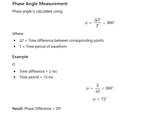
Phase Angle Measurement
In phase-angle measurements, the time difference between corresponding points of two waveforms is measured.
Parameters
| Symbol | Meaning |
|---|---|
| T₁ | Time difference between corresponding points |
| T | Time period of waveform |
| ϕ | Phase angle |
The phase angle is determined from the ratio of time difference to total time period.
Phase-Locked Loop (PLL)
A Phase-Locked Loop (PLL) is a feedback control system that synchronizes the output phase and frequency of an oscillator with a reference signal.
Main Components
Phase Detector
The phase detector compares:
- Input reference signal.
- Feedback signal from the VCO.
It produces an error signal proportional to the phase difference.
Low-Pass Filter
The low-pass filter smooths the error signal and removes unwanted high-frequency components.
Voltage Controlled Oscillator (VCO)
A VCO generates an output frequency determined by an applied control voltage.The control voltage is adjusted continuously until the VCO output frequency becomes synchronized with the reference signal.
Key Points
- Control voltage is applied to the VCO input.
- Phase detector compares VCO output with input reference frequency.
- PLL locks the oscillator frequency to the reference signal.
Voltage Controlled Oscillator (VCO)
A Voltage Controlled Oscillator produces an oscillation frequency that varies according to the applied control voltage.
Characteristics
- Frequency depends on input control voltage.
- Widely used in PLL systems.
- Provides frequency synchronization capability.
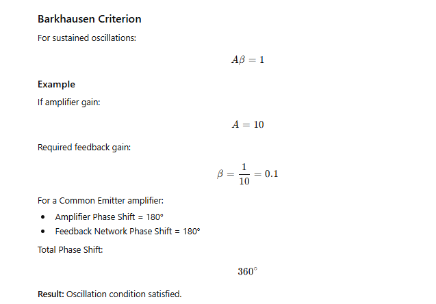
Oscillators and Barkhausen Criterion
For sustained oscillations, the Barkhausen Criterion must be satisfied.
Conditions
Magnitude Condition
The product of amplifier gain and feedback factor must be unity.
Phase Condition
The total phase shift around the loop must be either:
- 0°
- 360°
- Integral multiples of 360°
For a common-emitter amplifier:
- Amplifier contributes 180° phase shift.
- Feedback network must provide another 180° phase shift.
Example
If amplifier gain = 10,Feedback factor required = 0.1Feedback network phase shift = 180°
Crystal Oscillator
A crystal oscillator serves as the stable frequency reference in a frequency synthesizer.
Functions
- Generates highly stable frequency.
- Provides precise timing reference.
- Determines synthesizer frequency accuracy.
The stability of all synthesized frequencies depends upon the stability of the crystal oscillator.
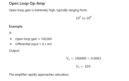
Operational Amplifiers
Open-Loop Configuration
An open-loop op-amp operates without feedback between output and input.
Characteristics
- Extremely high gain.
- Highly sensitive to small input voltage differences.
- Output usually saturates quickly.
- Nonlinear operation.
Features
- No feedback path.
- Very high open-loop gain.
- Output approaches supply limits for small input differences.
Op-Amp Differentiator
An op-amp differentiator produces an output proportional to the rate of change of input voltage.
Working
- Capacitor responds to changing input voltage.
- Current generated is proportional to the rate of change.
- Output voltage corresponds to the derivative of input signal.
Important Observation
For a constant input voltage, the rate of change is zero.Therefore:
- Output voltage becomes zero.
The capacitor blocks DC signals and only responds to changing input voltages.
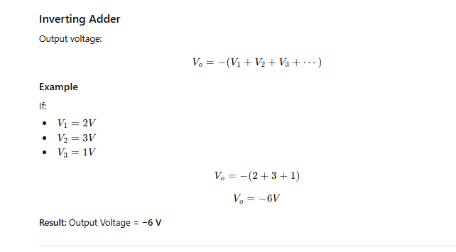
Inverting Op-Amp Adder
An inverting adder combines multiple input voltages at the inverting terminal.When all resistors are equal:
Output
The output voltage is equal to the negative sum of all input voltages.
Characteristics
- Performs analog summation.
- Produces inverted output.
- Widely used in analog computation.
Analog-to-Digital and Digital-to-Analog Conversion
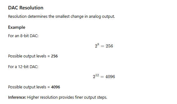
DAC Resolution
The resolution of a Digital-to-Analog Converter (DAC) determines the smallest change in analog output that can be produced.
Significance
- Higher resolution provides more output levels.
- Smaller output step size.
- Better analog signal reproduction.
- Improved precision.
Resolution does not directly determine:
- Power consumption.
- Maximum conversion speed.
- Maximum input voltage.
ADC Types
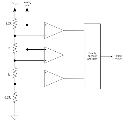
Flash ADC
Characteristics:
- Fastest ADC architecture.
- Uses parallel comparators.
- Performs conversion in a single step.
- Limited resolution.
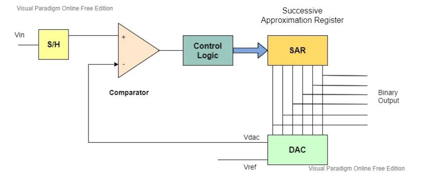
Successive Approximation ADC (SAR)
Characteristics:
- Moderate speed.
- Moderate resolution.
- Widely used.
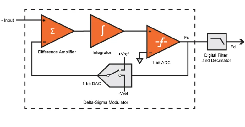
Sigma-Delta ADC
Characteristics:
- Very high resolution.
- Lower speed due to oversampling.
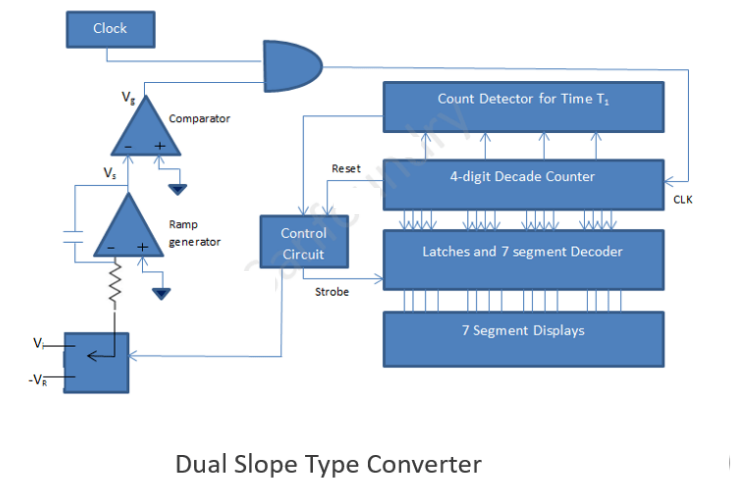
Dual-Slope ADC
Characteristics:
- Very high accuracy.
- Slowest conversion speed.
- Common in digital measuring instruments.
Comparison
| Feature | Flash ADC | Successive Approximation (SAR) ADC | Sigma-Delta (ΔΣ) ADC | Dual-Slope ADC |
|---|---|---|---|---|
| Conversion Speed | Fastest | Moderate | Slow | Slowest |
| Resolution | Low to Moderate | Moderate to High | Very High | High |
| Accuracy | Moderate | Good | Excellent | Excellent |
| Conversion Method | Parallel comparators | Binary search (successive approximation) | Oversampling & noise shaping | Integrate-deintegrate method |
| Hardware Complexity | Very High | Moderate | High | Low |
| Power Consumption | High | Moderate | Low to Moderate | Low |
| Number of Comparators | 2n−12^n - 12n−1 comparators | Single comparator | Few comparators | Single comparator |
| Cost | High | Moderate | Moderate to High | Low |
| Noise Immunity | Low | Moderate | Very High | Very High |
| Typical Resolution Range | 4–8 bits | 8–18 bits | 16–24+ bits | 12–20 bits |
| Main Advantage | Ultra-fast conversion | Good balance of speed and resolution | Highest resolution and precision | Highest accuracy with simple design |
| Main Limitation | Expensive and limited resolution | Not as fast as Flash | Slow due to oversampling | Very slow conversion |
| Common Applications | Radar, Oscilloscopes, High-speed communication | Microcontrollers, Data acquisition systems | Audio systems, Precision sensors, Instrumentation | Digital voltmeters, Multimeters, Measuring instruments |
 |  |  |  |
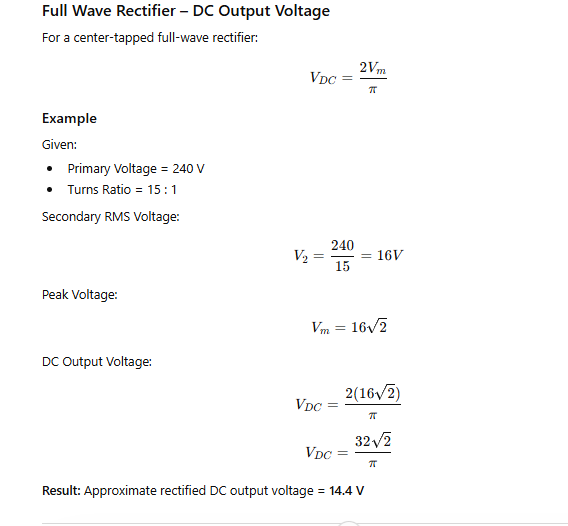
Rectifiers
Bridge Rectifier
A bridge rectifier converts AC to DC using four diodes.
Important Characteristics
| Parameter | Bridge Rectifier |
|---|---|
| Transformer Utilization Factor (TUF) | Higher |
| Ripple Factor | Same as center-tapped full-wave rectifier |
| Diode PIV Requirement | Lower |
Significance
Higher TUF indicates better transformer utilization compared with a center-tapped rectifier.
Ripple Factor and Capacitive Filters
Ripple factor represents the residual AC component present in rectifier output.
Minimizing Ripple
Ripple can be reduced by increasing filter effectiveness.
Important Point
Decreasing filter capacitance causes:
- Faster capacitor discharge.
- Greater voltage variation.
- Increased ripple factor.
Therefore, decreasing capacitance cannot minimize ripple.
Common Collector (CC) Amplifier
The common collector amplifier is also known as the emitter follower.
Characteristics
- Voltage gain approximately unity.
- Very high input impedance.
- Very low output impedance.
- High current gain.
- Suitable for impedance matching.
Important Observation
A CC amplifier is not a current-controlled current source.Its primary function is:
- Signal buffering.
- Impedance matching.
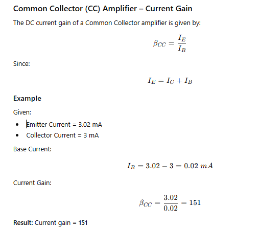
Current Gain of CC Amplifier
The DC current gain is determined from the ratio of emitter current to base current.
Example
If:
- Emitter current = 3.02 mA
- Collector current = 3.00 mA
Then:
- Base current = 0.02 mA
The current gain is obtained by dividing emitter current by base current.
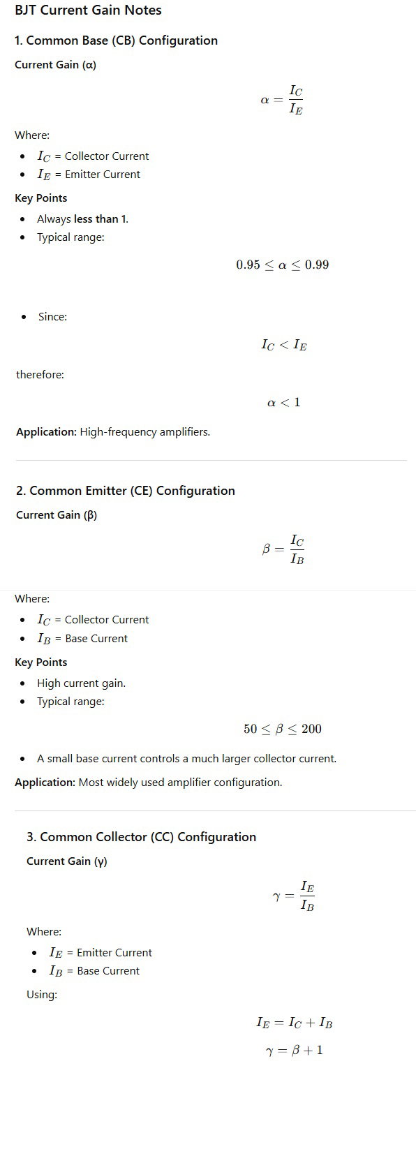
Common Base (CB) Amplifier
In the common-base configuration:
- Base terminal is common.
- Input is applied at emitter.
- Output is taken from collector.
Characteristics
- Low input impedance.
- High output impedance.
- Suitable for high-frequency operation.
Current Gain
The current gain (α) is:
- Collector current divided by emitter current.
- Always slightly less than unity.
Typical values range from approximately:
- 0.95 to 0.99
BJT Amplifier Configurations: CB vs CE vs CC
| Feature | Common Base (CB) | Common Emitter (CE) | Common Collector (CC) / Emitter Follower |
|---|---|---|---|
| Common Terminal | Base | Emitter | Collector |
| Input Applied At | Emitter-Base | Base-Emitter | Base-Collector |
| Output Taken From | Collector-Base | Collector-Emitter | Emitter-Collector |
| Voltage Gain | High | High | ≈ 1 (Unity) |
| Power Gain | Moderate | Very High | Moderate to High |
| Input Impedance | Very Low | Moderate | Very High |
| Output Impedance | Very High | High | Very Low |
| Phase Difference | 0° | 180° (Output Inverted) | 0° |
| Frequency Response | Excellent | Good | Good |
| Signal Buffering | Poor | Moderate | Excellent |
| Impedance Matching | Not Suitable | Moderate | Best Suitable |
| Main Application | RF & High-Frequency Amplifiers | General-Purpose Amplifiers | Buffer Circuits & Impedance Matching |
| Most Important Feature | Best High-Frequency Performance | Highest Overall Gain | Highest Input Impedance |
Superheterodyne Receiver
A superheterodyne receiver converts incoming RF signals into a fixed intermediate frequency (IF) for easier processing.
Signal Flow
| Stage | Function |
|---|---|
| Antenna | Receives RF signal |
| RF Stage | Amplifies desired signal |
| Mixer | Produces IF using local oscillator |
| IF Amplifier | Amplifies IF signal |
| Detector | Extracts information signal |
| Audio Amplifier | Drives output device |
Advantages
- High sensitivity.
- Good selectivity.
- Stable operation.
Thermocouples
A thermocouple operates on the Seebeck Effect, where an EMF is generated when two dissimilar metals experience a temperature difference.
Common Material Combination
- Copper
- Nickel-based alloy (Constantan)
Advantages
- Good thermoelectric sensitivity.
- Stable performance.
- Corrosion resistance.
- Moderate temperature measurement capability.
- Economical construction.
Battery Charging
In the constant voltage charging method, excessive charging voltage can lead to overcharging.
Effects of Overcharging
- Temperature rise.
- Thermal runaway.
- Electrolyte degradation.
- Reduced battery life.
- Safety hazards.
Proper voltage regulation is essential for safe and efficient battery operation.
Instrumentation Amplifier
A good instrumentation amplifier should possess:
- Finite and controllable gain.
- High accuracy.
- Reliable amplification of differential signals.
Important Characteristics
| Characteristic | Requirement |
|---|---|
| Gain | Finite |
| CMRR | High |
| Slew Rate | High |
| Power Consumption | Low |
High common-mode rejection enables effective rejection of unwanted noise while accurately amplifying the desired differential signal.
Important Numerical Examples
Common Collector (CC) Amplifier – Current Gain
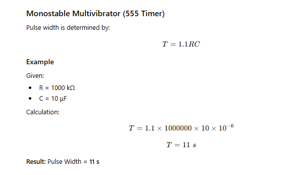
Monostable Multivibrator (555 Timer)
Full Wave Rectifier – DC Output Voltage
Phase Angle Measurement
Barkhausen Criterion
Inverting Adder
Open Loop Op-Amp
DAC Resolution
PLL Frequency Control
