OPTICAL COMMUNICATION, ELECTRONIC DEVICES, MEASUREMENTS, NETWORK THEORY AND ELECTRICAL MATERIALS
COMMUNICATION SYSTEMS, ELECTRONIC DEVICES, ELECTRICAL MATERIALS, MEASUREMENTS AND NETWORK THEORY
OPTICAL POWER METER (OPM)
An Optical Power Meter (OPM) is an instrument used to measure the power level of an optical signal in a fiber optic communication system. The measurement is generally expressed in decibels (dB), which indicate the relative strength of the optical signal.In a fiber optic link, a light source such as a laser transmits an optical signal through an optical fiber. At the receiving end, the optical power meter measures the incoming optical power level. This measurement is essential in telecommunication networks and fiber optic systems to ensure that adequate signal strength is maintained for reliable data transmission.The optical power meter measures optical signal power only. It is not used for spectroscopic analysis or optical fiber length measurement.
ACTIVE AND PASSIVE COMPONENTS
Active Components
Active components are devices capable of supplying or delivering energy to a circuit.Common active components include:
- Voltage sources
- Current sources
- Generators
- Bipolar Junction Transistors (BJTs)
- MOSFETs
- FETs
- JFETs
- Zener Diodes
- Photodiodes
- Schottky Diodes
- LEDs
These devices can control, amplify, or provide electrical energy within a circuit.
Passive Components
Passive components cannot continuously supply energy to a circuit. They either store energy temporarily or dissipate it.
Resistors
A resistor absorbs electrical energy and dissipates it as heat. It cannot supply energy to a circuit.
Capacitors
Capacitors store energy in the form of an electric field. The stored energy is limited and temporary.
Inductors
Inductors store energy in the form of a magnetic field and can return it to the circuit for a short duration only.
Transformers
A transformer transfers energy between circuits through electromagnetic induction. Although it can step up or step down voltage, the total power remains essentially unchanged. Since transformers do not generate energy, they are classified as passive components.
Electric Bulbs
An electric bulb requires electrical energy to produce light and therefore is not an active component.
RF SIGNAL STRENGTH MEASUREMENT
The strength of an RF signal at any point in a communication system is measured using a Field Strength Meter.A field strength meter detects electromagnetic fields produced by RF signals and converts them into measurable values. It is widely used in telecommunications, broadcasting, antenna testing, and RF engineering.
Features
- Measures RF signal strength accurately
- Supports various frequency ranges
- Useful for troubleshooting RF systems
- Helps optimize signal coverage
- Advanced models provide spectrum analysis
PERMANENT AND TEMPORARY MAGNETS
Permanent Magnets
Permanent magnets are manufactured using ferromagnetic materials possessing high coercivity and retentivity.Common materials used include:
- Platinum-Cobalt
- Alcomax
- Ticonal
- Carbon Steel
- Alnico
These materials retain magnetism for long periods.
Temporary Magnets
Temporary magnets are produced by passing current through a coil wound around a soft iron core.Characteristics:
- Magnetic strength exists only while current flows
- Cannot retain magnetism for long periods
- Commonly used as electromagnets
Electromagnets generally produce stronger magnetic fields than permanent magnets.
CORROSION OF METALS
Corrosion is the gradual deterioration of a metal caused by air, moisture, or chemical action.
Examples
- Rusting of iron
- Green coating on copper
- Tarnishing of silver
Methods of Prevention
- Painting
- Oiling
- Galvanization
- Chrome Plating
- Anodising
Factors Affecting Corrosion
- Reactivity of metal
- Air and moisture
- Mechanical strains
- Presence of electrolytes
- Presence of impurities
RELAY
A relay is a protective and control device that senses abnormal conditions and sends operating information to a circuit breaker for circuit interruption.A relay functions as an electrically operated switch capable of opening or closing circuits automatically without human intervention.
Functions
- Detect faults
- Control high-power circuits using low-power signals
- Initiate circuit breaker operation
- Provide automatic switching
IDEAL (PERFECT) CONDUCTOR
An ideal conductor is a hypothetical conductor possessing:
- Infinite conductivity
- Zero resistance
- Zero voltage drop
Only a very small voltage is required to carry an extremely large current.
Properties
- Electric field inside the conductor is zero
- Magnetic field inside the conductor is zero
- Net charge density inside is zero
- Excess charge resides only on the surface
- Entire conductor remains at the same potential
- Electric field exists outside the conductor
An ideal conductor does not exist in practice.
HOLE CONDUCTION IN SEMICONDUCTORS
In semiconductors, electrons may gain energy and move from the valence band to the conduction band.This transition leaves behind a vacancy called a hole.Although a hole is merely the absence of an electron, it behaves as a positive charge carrier. When neighboring electrons move to fill the vacancy, the hole appears to move in the opposite direction.This movement of holes contributes to electrical conduction and is known as hole conduction.
COUPLING METHODS IN AMPLIFIERS
The purpose of coupling is:
- To transfer AC signals from one stage to another
- To block DC components between stages
Transformer Coupling
Transformer coupling uses a transformer as the coupling element.Characteristics:
- No coupling capacitor required
- Provides impedance matching
- Offers highest gain
- Efficient power transfer
Impedance Coupling
Uses inductors and capacitors as coupling elements.The impedance of the coupling coil depends on frequency and inductance.This method is not widely used.
RC Coupling
RC coupling uses a resistor-capacitor network.Characteristics:
- Most widely used coupling method
- Capacitor passes AC
- Capacitor blocks DC
FOUR-TERMINAL METHOD FOR LOW RESISTANCE MEASUREMENT
The Four-Terminal Method (Kelvin Method) is used for accurate measurement of very low resistances.In low-resistance measurements, lead resistance and contact resistance can significantly affect accuracy.The four-terminal arrangement separates:
- Current-carrying path
- Voltage-sensing path
This arrangement eliminates the influence of:
- Lead resistance
- Contact resistance
- Parasitic resistance
Thus, highly accurate low-resistance measurements become possible.
SPECIAL PURPOSE DIODES
Varactor Diode
A varactor diode is a PN junction diode whose capacitance varies with reverse voltage.
Tunnel Diode
A tunnel diode is a heavily doped semiconductor device capable of extremely fast operation.Applications:
- Frequency detectors
- Frequency converters
Zener Diode
A Zener diode operates in the reverse breakdown region.Characteristics:
- Maintains constant voltage
- Used as a voltage regulator
TRANSFORMER CORE LAMINATIONS
Transformer cores are made from thin laminated sheets to reduce eddy current losses.
Typical Lamination Thickness
- 0.25 mm to 0.5 mm
The lamination structure consists of:
- Varnish
- Silicon steel
- Varnish
Insulation between laminations provides electrical isolation and reduces eddy current losses.The process of assembling laminations is known as Core Staggering.
SOLID-STATE RELAY (SSR)
A solid-state relay is an electronic switching device that uses semiconductor components instead of moving contacts.
Characteristics
- No moving parts
- Fast switching
- High reliability
- Long operating life
- Controlled by a small input voltage
Applications include:
- Digital circuits
- Telecommunication systems
- Industrial automation
VALENCE ELECTRONS AND ELECTRICAL CONDUCTIVITY
Valence electrons determine the electrical conductivity of a material.The outermost shell of an atom is known as the Valence Shell.A valence shell can contain up to eight electrons.
Classification Based on Valence Electrons
Conductors
- Less than four valence electrons
- High conductivity
Semiconductors
- Four valence electrons
- Intermediate conductivity
Insulators
- More than four valence electrons
- Poor conductivity
CLAMPER CIRCUITS
A clamper circuit changes the DC level of a waveform without changing its shape.
Functions
- Shifts waveform upward or downward
- Maintains waveform shape
- Establishes desired DC reference level
Clipper vs Clamper
A clipper removes a portion of the waveform above or below a specified reference level.A clamper shifts the entire waveform without removing any portion.
ENVELOPE DETECTOR
An envelope detector is used for AM demodulation.Characteristics:
- Low-pass filter based detector
- Asynchronous detection
- Suitable when modulation index ≤ 1
The output follows the envelope of the modulating signal.When modulation index exceeds unity, synchronous detection is preferred.
TRANSFORMER COUPLING LIMITATIONS IN AUDIO AMPLIFIERS
Transformer coupling is not commonly used in modern audio amplifiers because:
- Large size and weight
- High cost
- Limited frequency response
- Distortion at high and low frequencies
- Reduced efficiency due to power losses
Modern solid-state circuits generally provide superior performance.
GUNN DIODE
A Gunn diode is a Transferred Electron Device (TED) and a negative resistance device.Characteristics:
- Contains only N-type semiconductor material
- No PN junction
- Generates microwave frequencies
- Majority carriers are electrons
Materials Used
- Gallium Arsenide (GaAs)
- Indium Phosphide (InP)
Advantages
- High bandwidth
- High reliability
- Low cost
- Fair noise performance
- Low operating voltage
Disadvantages
- Poor stability
- High FM noise
- Small tuning range
- Low efficiency below 10 GHz
FUSE
The primary purpose of a fuse is overcurrent protection.A fuse contains a conducting element that melts when current exceeds its rated value.
Functions
- Opens the circuit during excessive current
- Protects equipment from damage
- Prevents overheating and fire hazards
Fuses respond to excessive current, not directly to excessive voltage.
ISOTROPIC ANTENNA
An isotropic antenna is a hypothetical antenna that radiates equally in all directions.
Characteristics
- Uniform radiation pattern
- Gain = 1
- Gain = 0 dB
- Reference antenna for antenna measurements
Its radiation pattern is represented by a sphere.
ISDN (INTEGRATED SERVICES DIGITAL NETWORK)
ISDN is a digital communication system capable of carrying voice, video, and data over a single communication line.
Services
Bearer Service
Transfers voice, video, and data without network manipulation.
Teleservice
Includes:
- Telephone service
- Teletex
- Videotex
- Teleconferencing
Supplementary Services
Includes:
- Call waiting
- Reverse charging
- Message handling
Advantages
- Digital communication
- Fast connectivity
- Voice, video, and data integration
- High data transfer rate
- Multiple devices on one line
- Conference calling facilities
Drawbacks
- Difficult installation
- Obsolete in many applications
- Reliability concerns
- Replaced increasingly by VoIP technologies
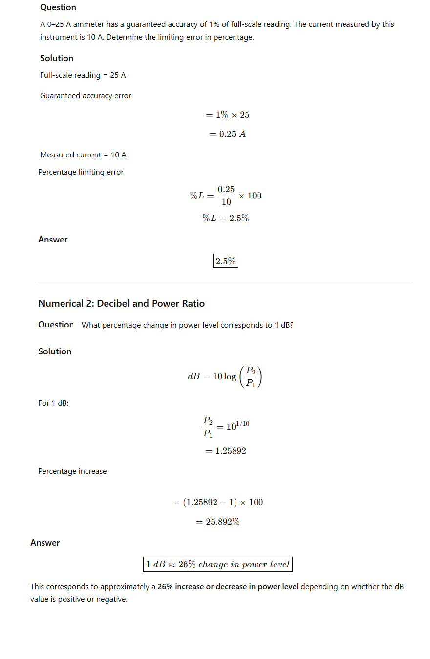
NUMERICAL EXAMPLES
Numerical 1: Limiting Error in Ammeter