COMMUNICATION SYSTEM
COMMUNICATION SYSTEM – COMPLETE NOTES
Communication Modes
Full Duplex Communication
In Full Duplex Mode, communication is bidirectional, meaning data transmission takes place in both directions simultaneously.This mode allows two devices to transmit and receive information at the same time. Full duplex communication is commonly used in:
- Telephone networks
- Internet communication systems
- Modern digital communication systems
Full duplex differs from Half Duplex Communication, where data can travel in both directions but not simultaneously.
Other Communication Modes
| Communication Type | Description |
|---|---|
| Unidirectional | Communication occurs only in one direction |
| Half Duplex | Communication occurs in both directions but not simultaneously |
| Full Duplex | Communication occurs simultaneously in both directions |
Unidirectional Communication
Communication takes place only in one direction.Example:
- Traditional radio broadcasting
Multidirectional Communication
This term is not generally used for duplex communication systems.
Tridirectional Communication
This is not a standard communication system term.
Modulation in Communication Systems
Role of Modulator
The primary role of a Modulator is to:
Superimpose the Message Signal onto the Carrier Wave
Modulation combines:
- Low-frequency message signal
- High-frequency carrier signal
The process modifies one characteristic of the carrier wave according to the message signal.
Purpose of Modulation
- Efficient long-distance transmission
- Multiplexing of signals
- Improved noise immunity
- Better antenna size compatibility
Amplitude Modulation (AM)
Modulation Index
The Modulation Index (m) determines the extent of variation of carrier amplitude by the message signal.
Conditions of Modulation Index
| Modulation Index | Condition |
|---|---|
| m = 0 | Carrier is unmodulated |
| m = 1 | 100% modulation |
| m > 1 | Overmodulation occurs |
As the modulation index increases:
- Amplitude variation increases
- Peak-to-peak amplitude increases
Overmodulation
When:
m > 1
the AM signal becomes distorted because the envelope no longer accurately represents the message signal.
Double Sideband Suppressed Carrier (DSB-SC)
Definition
In DSB-SC, the carrier is suppressed and only the sidebands carry information.
Generation of DSB-SC
DSB-SC is generated using:
- Balanced Modulator
- Ring Modulator
These modulators multiply the message signal with the carrier signal while suppressing the carrier component.
Output of Balanced/Ring Modulator
The output contains:
- Upper Sideband (USB)
- Lower Sideband (LSB)
Carrier frequency is suppressed.
Additional Processing Requirement
| Modulation Type | Additional Processing |
|---|---|
| DSB-SC | Not required |
| SSB-SC | Filtering required |
| VSB | Partial filtering required |
Vestigial Sideband (VSB) Modulation
Definition
Vestigial Sideband Modulation is a form of amplitude modulation in which:
- One sideband is transmitted completely
- A small portion of the other sideband is also transmitted
VSB reduces bandwidth while preserving important signal information.
Application
VSB is widely used in:
Television Broadcasting
VSB Demodulation
Correct Demodulation Method
Product Modulator followed by Low-Pass Filter
Working Principle
Step 1: Product Modulation
The received VSB signal is multiplied with a locally generated carrier signal.This shifts the signal back to the baseband frequency range.
Step 2: Low-Pass Filtering
After multiplication:
- Desired baseband signal
- High-frequency components
are produced.The low-pass filter removes unwanted high-frequency components and recovers the original modulating signal.
Advantages of VSB
- Reduced bandwidth requirement
- Efficient signal recovery
- Suitable for television transmission
Synchronous Detection in DSB-SC
Principle
Synchronous detection uses a locally generated carrier at the receiver for demodulation.For accurate demodulation:
- Frequency must match
- Phase must match
with the transmitted carrier.
Phase Error in Synchronous Detection
Cause
A phase difference between:
- Transmitted carrier
- Local carrier
creates phase error.
Mathematical Expression
Transmitted Signal
s(t)=Acos(ωct)
Local Carrier
cos(ωct+θ)
Demodulated Output
After multiplication and filtering: y(t)=0.5Am(t)cos(θ)
Effects of Phase Error
Phase error causes:
- Reduction in output amplitude
- Phase distortion
The amplitude gets multiplied by:
cos(θ)
Thus output decreases when phase mismatch increases.
Frequency Modulation (FM)
Wide Band Frequency Modulation (WBFM)
Wideband FM is used in:
FM Broadcasting
In WBFM, the carrier frequency deviation is large to achieve high-quality audio transmission.
Maximum Frequency Deviation
75 kHz
This is the standard deviation used in FM broadcasting systems.
Audio Baseband Bandwidth
15 kHz
Carson’s Rule
The bandwidth of an FM signal is estimated using Carson’s Rule.
B=2(Δf+fm)
Where:
- B = Total Bandwidth
- Δf = Maximum Frequency Deviation
- fm = Maximum Modulating Frequency
FM Broadcast Bandwidth Calculation
Using:
- Δf = 75 kHz
- fm = 15 kHz
B=2(75 kHz+15 kHz)=180 kHz
Thus FM broadcasting occupies approximately:
180 kHz bandwidth
FM Broadcast Frequency Band
FM broadcasting operates within:
88 MHz – 108 MHz
Each FM station is allocated:
200 kHz bandwidth
Advantages of FM over AM
| Property | AM | FM |
|---|---|---|
| Noise Immunity | Low | High |
| Bandwidth | Narrow | Wide |
| Power Efficiency | Low | High |
Noise Immunity
FM provides better noise immunity because information is carried through frequency variation rather than amplitude variation.
Bandwidth
AM requires lower bandwidth compared to FM.
Power Efficiency
FM utilizes transmitted power more efficiently because all transmitted power carries information.In AM:
- Significant power is wasted in the carrier.
Demodulation
Definition
Demodulation is the process of recovering the original information signal from the modulated carrier wave.
Characteristics of Demodulation
Performed at Receiving End
Demodulation occurs after the signal reaches the receiver.
Recovery of Original Signal
It extracts the original low-frequency message signal from the carrier wave.
Digital Modulation
Definition
Digital modulation modifies a carrier signal to represent digital information.Carrier properties modified include:
- Amplitude
- Frequency
- Phase
Phase Shift Keying (PSK)
Definition
PSK is a digital modulation technique in which the phase of the carrier signal is varied according to digital data.
Types of PSK
Binary Phase Shift Keying (BPSK)
Uses two phase states:
- 0°
- 180°
to represent binary digits.
Quadrature Phase Shift Keying (QPSK)
Uses four phase states:
- 0°
- 90°
- 180°
- 270°
Each symbol represents two bits.
Higher-Order PSK
Examples:
- 8-PSK
- 16-PSK
These increase data transmission rate by transmitting more bits per symbol.
Advantages of PSK
- High spectral efficiency
- Better noise performance
- Suitable for modern communication systems
Applications of PSK
PSK is used in:
- Wi-Fi systems
- Cellular communication
- Satellite communication
- Optical fiber communication
Analog Modulation Techniques
| Technique | Type |
|---|---|
| Single Sideband (SSB) | Analog |
| Narrow Band FM | Analog |
| Double Sideband AM | Analog |
| PSK | Digital |
Raised Cosine Filter
Definition
The Raised Cosine Filter is used in digital communication systems to minimize:
Inter Symbol Interference (ISI)
ISI occurs when adjacent pulses overlap and create errors during detection.
Working Principle
The raised cosine filter shapes the transmitted signal such that:
Zero ISI occurs at sampling instants
Roll-Off Factor (α)
The filter is characterized by the roll-off factor:
0 ≤ α ≤ 1
Conditions
| Roll-Off Factor | Condition |
|---|---|
| α = 0 | Ideal sharp cut-off |
| α = 1 | Wide transition band |
Importance of Raised Cosine Filter
- Reduces ISI
- Improves symbol detection
- Maintains signal integrity
- Essential in digital communication systems
QUICK REVISION
Full Duplex
- Simultaneous bidirectional communication
DSB-SC
- Carrier suppressed
- Sidebands carry information
- Generated using balanced/ring modulator
VSB Demodulation
- Product modulator + low-pass filter
FM Broadcasting
- Maximum deviation = 75 kHz
- Frequency band = 88–108 MHz
Demodulation
- Performed at receiver
- Recovers original signal
PSK
- Digital modulation technique
- Information represented by phase changes
Raised Cosine Filter
- Minimizes intersymbol interference
- Provides zero ISI at sampling instants
Phase-Locked Loop (PLL) and FSK Demodulation
A Phase-Locked Loop (PLL) continuously tracks the frequency variations of an incoming signal. In FSK demodulation, whenever the input frequency changes, the PLL automatically adjusts the frequency of its Voltage-Controlled Oscillator (VCO) to lock onto the incoming signal.
Important Points
- PLL tracks changes in the frequency of the modulated signal.
- VCO frequency continuously adjusts to match the input frequency.
- PLL is widely used for FSK demodulation.
- The demodulated output is obtained from the PLL control voltage.
PLL-Based FM Demodulator
In a PLL FM demodulator, the Phase Detector compares:
- Incoming FM signal
- VCO output signal
The phase detector produces an output voltage proportional to the phase difference between these signals.
Working
- FM signal is applied to the phase detector.
- Phase detector compares it with VCO output.
- Output voltage varies according to phase difference.
- Frequency variations of FM appear as phase variations.
- After low-pass filtering, the original message signal is recovered.
Important Point
The phase detector primarily detects phase difference, not amplitude.
Phase Modulation (PM)
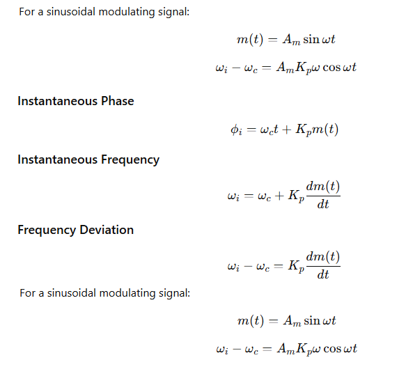
Observation
The frequency deviation in PM is proportional to:
- Modulating signal amplitude
- Modulating signal frequency
Frequency Modulation (FM)
In Frequency Modulation, the carrier frequency varies according to the message signal.
Applications
- FM radio broadcasting
- Two-way radio communication
- Television audio transmission
- Data communication systems
Major Advantage
FM provides better noise immunity compared to amplitude modulation.
Carson's Rule
Carson's Rule estimates the bandwidth required for an FM signal.[
BT=2(Δf+fm)
Where:
- Δf = Peak frequency deviation
- fm = Maximum modulating frequency
Example
Given:
- Δf = 5 kHz
- fm = 3 kHz
BT=2(5+3)=16kHz
Result
Required FM bandwidth = 16 kHz.
Narrowband FM (NBFM)
Characteristics
- Small frequency deviation (typically ±5 kHz or less)
- Small bandwidth
- Suitable for voice communication
Applications
- Police communication
- Ambulance communication
- Taxi communication
- Aviation VHF radios
- Marine communication systems
- Amateur radio communication
Frequency Shift Keying (FSK)
FSK is a digital modulation technique in which the carrier frequency changes according to the binary data.
Operation
- Binary 1 → Higher frequency (Mark Frequency)
- Binary 0 → Lower frequency (Space Frequency)
Features
- Better noise immunity than AM.
- Simple implementation.
- Reliable data transmission.
Differential Phase Shift Keying (DPSK)
DPSK is a variation of PSK in which phase changes are measured relative to the previous symbol instead of a fixed reference.
Advantage
- Eliminates phase ambiguity problems.
- Does not require an absolute phase reference.
Amplitude Modulation Variants
Double Sideband Suppressed Carrier (DSB-SC)
Features
- Carrier is suppressed.
- Both sidebands are transmitted.
- Generated using a balanced modulator.
Output Contains
- Upper Sideband (USB)
- Lower Sideband (LSB)
- Modulation frequency components
Advantage
- More power efficient than conventional AM.
Single Sideband (SSB)
Features
- Only one sideband is transmitted.
- Carrier is suppressed.
Advantages
- Maximum bandwidth efficiency.
- Maximum power efficiency.
Applications
- HF communication
- Military communication
- Long-distance radio communication
Vestigial Sideband (VSB)
Features
- One sideband transmitted completely.
- Other sideband transmitted partially.
Advantages
- Reduced bandwidth.
- Simple envelope detection.
Application
- Television video transmission.
Pulse Modulation Techniques
Pulse Time Modulation (PTM) involves varying time-related pulse parameters according to the modulating signal.
Pulse Width Modulation (PWM)
Characteristics
- Pulse width varies.
- Amplitude remains constant.
Also Known As
- Pulse Duration Modulation (PDM)
- Pulse Length Modulation (PLM)
Applications
- Motor speed control
- LED dimming
- DC-DC converters
Pulse Position Modulation (PPM)
Characteristics
- Information is carried by pulse position.
- Pulse amplitude remains constant.
- Pulse width remains constant.
Advantages
- Good noise immunity.
- Less affected by amplitude variations.
Applications
- Optical communication systems
- Telemetry systems
- Fiber-optic communication
PPM Generation
- Message signal and sawtooth signal are compared.
- PAM is generated.
- Monostable multivibrator converts PAM into PPM.
- Pulse position varies according to message amplitude.
Eye Diagram
An Eye Diagram is a graphical tool used to evaluate digital communication system performance.
Applications
- Investigation of Inter-Symbol Interference (ISI).
- Determination of optimum sampling instant.
- Evaluation of signal quality.
Important Features
Eye Opening Width
Represents the time interval where the signal can be sampled without ISI.
Wide Eye Opening
- Less distortion.
- Lower error probability.
Narrow Eye Opening
- Higher ISI.
- Greater probability of errors.
Observation Equipment
Eye diagrams are typically observed using a Digital Storage Oscilloscope (DSO).
Guided Transmission Media
Guided media use a physical path for signal transmission.
Optical Fibre
Construction
- Core
- Cladding
Working
Light travels through the core and is continuously reflected by the cladding.
Advantages
- High bandwidth
- Low attenuation
- High efficiency
- Immunity to electromagnetic interference
Non-Guided Media
- Radio waves
- Satellite communication
- Infrared transmission
Superheterodyne Receiver
A superheterodyne receiver converts the incoming RF signal into a fixed Intermediate Frequency (IF).
Intermediate Frequency
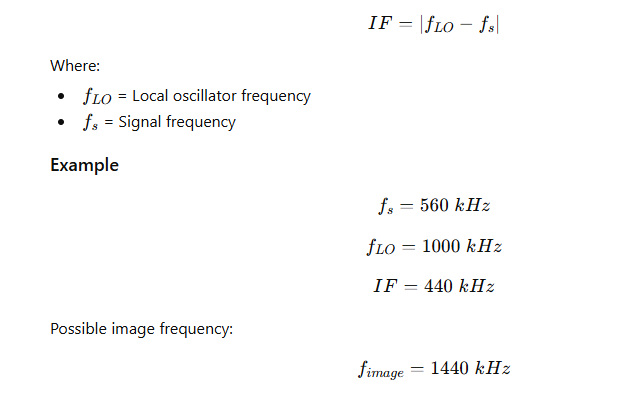
Image Frequency
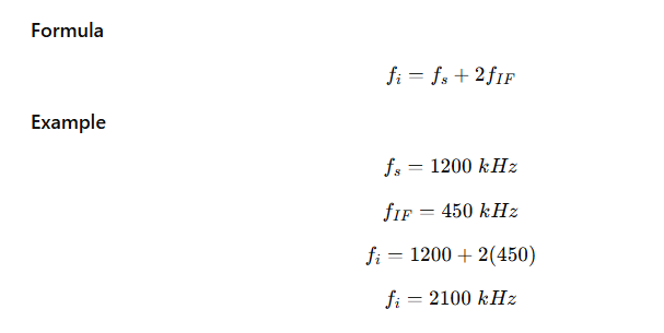
Image frequency is an unwanted frequency that also produces the same intermediate frequency and causes interference.
Formula
Phase Shift and Time Delay
For periodic signals:
360° Phase Shift
A phase shift of 360° corresponds to one complete cycle.
Relation
[
\Delta t = T
]Where:
- Δt = Time delay
- T = Signal period
Conclusion
A 360° phase shift produces a time delay equal to one period.
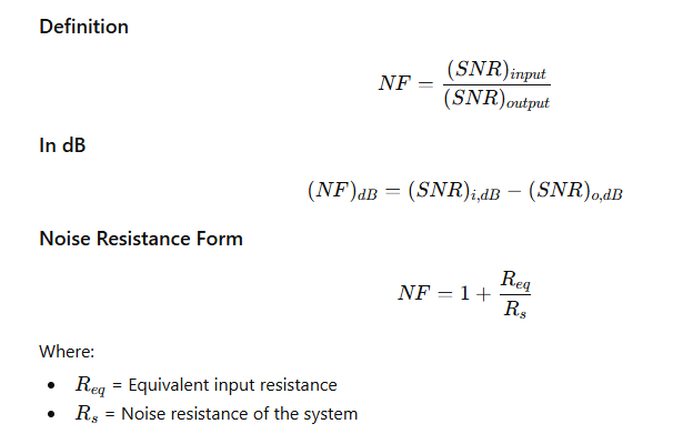
Noise Figure (NF)
Noise Figure measures degradation in the Signal-to-Noise Ratio (SNR) caused by system components.
Definition
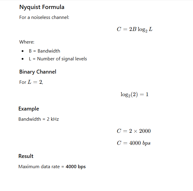
Channel Capacity
Nyquist Formula
For a noiseless channel:
Time Division Multiplexing (TDM)
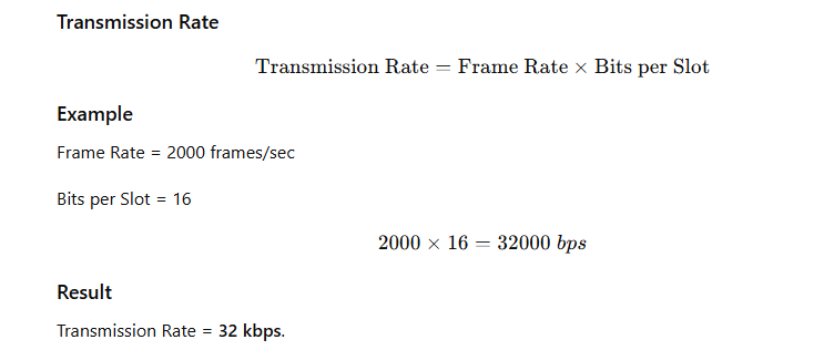
TDM combines multiple data streams into a single transmission channel by allocating different time slots.
Transmission Rate