Pure Resistive, Pure Capacitive & Pure Inductive Circuits
Pure Resistive, Pure Capacitive & Pure Inductive Circuits
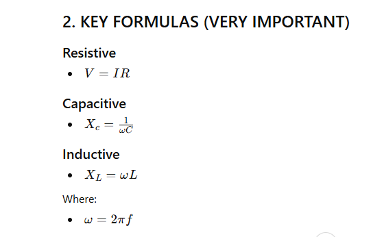
1. COMPARATIVE TABLE
| Property | Pure Resistive Circuit | Pure Capacitive Circuit | Pure Inductive Circuit |
|---|---|---|---|
| Element | Resistor (R) | Capacitor (C) | Inductor (L) |
| Opposition to Current | Resistance (R) | Capacitive Reactance (Xc) | Inductive Reactance (XL) |
| Formula | R | Xc = 1 / (ωC) | XL = ωL |
| Phase Relation (V–I) | Voltage & Current in phase | Current leads voltage by 90° | Current lags voltage by 90° |
| Phase Angle (θ) | 0° | -90° | +90° |
| Power Consumption | Real power consumed | No real power (only reactive) | No real power (only reactive) |
| Power Factor | 1 (Unity) | 0 (Leading) | 0 (Lagging) |
| Energy Storage | No storage (dissipates as heat) | Stores energy in electric field | Stores energy in magnetic field |
| Impedance (Z) | Z = R | Z = Xc | Z = XL |
| Frequency Effect | No effect | Xc decreases with frequency | XL increases with frequency |
| Current Behavior | Same waveform as voltage | Current peaks earlier | Current peaks later |
3. MEMORY TRICKS
- Resistive → SAME phase (0°)
- Capacitive → Current LEADS (ICE)
- Inductive → Current LAGS (ELI)
👉 Trick:
- ELI → Voltage leads in Inductor
- ICE → Current leads in Capacitor
Comments