RRB TECHNICAL
PART 1
1. Title Block in Engineering Drawings
Definition
A Title Block is an essential component of an engineering drawing sheet that provides important information regarding the drawing and the project it represents. It serves as a reference for identification, documentation, communication, and standardization, enabling engineers, manufacturers, project managers, and other stakeholders to easily understand and use the drawing.
Standard Location
The Title Block is placed in the bottom right-hand corner of the drawing sheet. This location is universally accepted because it provides quick and convenient access to essential drawing information.
Contents of a Title Block
A typical title block contains the following information:
- Drawing Title – Name or description of the drawing.
- Drawing Number – Unique identification number of the drawing.
- Scale – Ratio between the drawing size and the actual size.
- Date – Date of creation or revision.
- Name of Drafter – Person who prepared the drawing.
- Approval Details – Review and approval signatures or stamps.
- Company Logo – Name or logo of the organization.
- Project Information – Project name, project code, or contract number.
Importance
The title block plays a significant role in engineering documentation because it:
- Provides identification of the drawing and project.
- Ensures standardization across all engineering drawings.
- Facilitates proper documentation for manufacturing, construction, and assembly.
- Maintains version control by recording revisions.
- Enhances the professional appearance and credibility of engineering drawings.
Standardization of Contents
Certain information such as the drawing title, drawing number, scale, and date follows standard conventions. However, organizations are free to customize the title block according to their own requirements.Customization may include:
- Company logo
- Project-specific codes
- Revision history
- Approval signatures
- Additional organization-specific information
Examination Point
Statement Analysis
Statement 1: The title block is located at the bottom right-hand corner of the drawing sheet.
→ TrueStatement 2: The contents of the title block are completely standardized and cannot be modified according to company requirements.
→ False
Correct Answer
Statement 1 is true, but Statement 2 is false.
2. 10 mm Single-Stroke Capital Letters (Vertical Style)
Definition
In single-stroke vertical lettering, two horizontal parallel guide lines are drawn to maintain uniform lettering. The 10 mm distance between these parallel lines represents the height of the capital letters.
Letter Height
The letter height is the vertical dimension of the capital letters and is determined by the spacing between the two horizontal guide lines.For 10 mm lettering, the distance between the guide lines is 10 mm, ensuring uniformity and readability.
Characteristics of Single-Stroke Lettering
Single-stroke lettering is characterized by:
- Uniform stroke thickness.
- Letters formed using single continuous strokes.
- Upright (vertical) orientation.
- Standardized size for consistency.
- Improved clarity and readability in engineering drawings.
Importance of Letter Height
Maintaining a standard letter height:
- Ensures uniform appearance.
- Improves legibility.
- Maintains standardization in technical drawings.
- Facilitates accurate interpretation of engineering documents.
Distinction Between Related Terms
| Term | Meaning |
|---|---|
| Letter Height | Vertical size of each letter. |
| Interline Spacing | Distance between two successive lines of text. |
| Letter Width | Horizontal dimension of a letter; varies with the character. |
| Stroke Thickness | Thickness of the line used to draw the letter. |
Examination Point
10 mm distance between horizontal parallel guide lines = Letter Height
Correct Answer
Letter Height
3. Null Method of Measurement
Definition
The Null Method is a highly accurate calibration and measurement technique in which the unknown quantity is balanced against a known standard until the difference becomes zero (null point).
Principle
The null method works on the principle of opposition. Measurement is achieved by balancing the unknown value with a standard reference until no difference exists between them.
Accuracy
The method offers very high accuracy because it:
- Eliminates errors due to instrument resistance.
- Minimizes loading effects.
- Depends on achieving a zero balance rather than direct measurement.
Advantages
- High measurement accuracy.
- Reduced instrument errors.
- Reliable calibration.
- Suitable for precision measurements.
Applications
Examples include:
- Wheatstone Bridge – Measurement of unknown resistance.
- Potentiometer – Measurement of EMF of a cell.
Examination Point
Most accurate calibration technique:Null Method
4. Electrodynamometer-Type Power Factor Meter
Definition
An Electrodynamometer-Type Power Factor Meter is an AC measuring instrument used to determine the power factor of electrical circuits.
Main Advantage
Its primary advantage is its ability to measure the power factor of both single-phase and three-phase circuits.
Working Features
The instrument:
- Operates without control springs.
- The moving system is controlled entirely by the ratio of magnetic forces produced by two coils.
- When disconnected, the pointer remains in its last position because no restoring spring is provided.
Advantages
- Suitable for single-phase circuits.
- Suitable for three-phase circuits.
- High measurement accuracy.
- Sensitive to phase difference between voltage and current.
Examination Point
Main Advantage: Measures both single-phase and three-phase power factors.
5. 8051 Register Bank Switching
Definition
The 8051 Microcontroller contains four register banks in its internal RAM. Register bank switching allows the processor to quickly change from one set of registers to another, significantly improving the efficiency of Interrupt Service Routines (ISRs).
Register Banks
The first 128 bytes of internal RAM contain:
- Bank 0
- Bank 1
- Bank 2
- Bank 3
Each bank contains eight registers (R0–R7).
Traditional Context Switching
In most microcontrollers:
- Register contents are pushed onto the stack during an interrupt.
- After ISR execution, they are popped back.
- This process consumes additional clock cycles.
Register Bank Switching in 8051
Instead of repeatedly using stack operations, the 8051 simply changes the active register bank by modifying the RS1 and RS0 bits in the Program Status Word (PSW).The ISR can immediately start using another register bank while the previous bank remains unchanged.
Advantages
- Faster interrupt execution.
- Eliminates multiple push/pop operations.
- Reduces execution time.
- Improves ISR efficiency.
Examination Point
Efficiency is improved because of Register Bank Switching.
6. Types of Lines
Engineering drawing uses different types of lines depending upon their orientation and purpose.
| Line Type | Description |
|---|---|
| Horizontal Line | Parallel to the horizontal plane; extends left to right with zero slope. |
| Vertical Line | Perpendicular to horizontal lines; extends from top to bottom. |
| Inclined Line | Neither horizontal nor vertical; makes an angle with the horizontal plane. |
| Curved Line | Continuously changes direction; used for arcs, circles, ellipses, and irregular shapes. |
Matching
| Description | Line Type |
|---|---|
| Neither parallel nor perpendicular to horizontal plane | Inclined Line |
| Perpendicular to horizontal lines | Vertical Line |
| Changes direction continuously | Curved Line |
| Parallel to horizontal plane | Horizontal Line |
Correct Matching
A–3, B–2, C–4, D–1
7. Prick Punch
Definition
A Prick Punch is a pointed hand tool used in metalworking to produce small indentations on a workpiece. These marks serve as guides for drilling or further machining operations.
Grinding Angle
The point of a prick punch is ground at an angle of 30°.
Importance of 30° Angle
A 30° point angle:
- Produces sharp and precise indentations.
- Requires less force.
- Minimizes slipping.
- Improves marking accuracy.
- Provides a balance between sharpness and durability.
- Is the standard angle used in engineering practice.
Applications
Used for:
- Layout marking.
- Drilling guides.
- Precision marking on metal surfaces.
Examination Point
Standard grinding angle of Prick Punch = 30°
8. Differential Amplifier
Definition
A Differential Amplifier amplifies the difference between two input signals while rejecting signals that are common to both inputs.
Main Advantage
The principal advantage is its ability to reject common-mode signals (noise) while amplifying only the differential signal.
Common Mode Rejection Ratio (CMRR)
A differential amplifier possesses a high Common Mode Rejection Ratio (CMRR), which significantly reduces unwanted noise appearing simultaneously at both inputs.
Benefits
- Excellent noise rejection.
- Cleaner output signal.
- Higher measurement accuracy.
- Improved signal quality.
Examination Point
Main Advantage:Rejects common-mode signals while amplifying differential signals.
9. Inductive Proximity Sensor
Definition
An Inductive Proximity Sensor is designed exclusively for the detection of metallic objects.
Working Principle
The sensor generates a high-frequency electromagnetic field.When a metallic object enters this field:
- Eddy currents are induced in the metal.
- These eddy currents create an opposing magnetic field.
- Oscillation amplitude decreases.
- The sensor detects this change and produces an output.
Detectable Material
Among the given materials, the sensor detects:
- Stainless Steel
Non-Detectable Materials
The following materials do not generate eddy currents:
- Wood
- Glass
- Paper
Therefore, they cannot be detected by an inductive proximity sensor.
Examination Point
Inductive Proximity Sensor detects only metallic objects.
10. End Standard
Definition
An End Standard is a measuring standard in which the measurement is determined by the distance between two parallel flat surfaces.Examples include Slip Gauges, End Bars, and Micrometer Measuring Faces.
Characteristics
An End Standard:
- Measures distance between parallel flat faces.
- Provides high measurement accuracy.
- Is widely used for precision calibration and dimensional inspection.
Difference Between Line Standard and End Standard
| Line Standard | End Standard |
|---|---|
| Measures distance between two engraved lines. | Measures distance between two parallel flat surfaces. |
| Example: Steel Rule | Example: Slip Gauge |
Examination Point
Incorrect Statement
"It is used to measure the distance between two engraved lines."This statement is incorrect because it describes a Line Standard, not an End Standard.
Quick Revision Table
| Topic | Important Fact |
|---|---|
| Title Block | Bottom right corner of drawing sheet |
| 10 mm Lettering | 10 mm = Letter Height |
| Null Method | Measurement by zero balance |
| Power Factor Meter | Measures both single & three phase PF |
| 8051 ISR | Register Bank Switching increases speed |
| Line Types | A–3, B–2, C–4, D–1 |
| Prick Punch | Point angle = 30° |
| Differential Amplifier | High CMRR, rejects common-mode noise |
| Inductive Sensor | Detects metallic objects only |
| End Standard | Measures distance between parallel flat surfaces |
PART 2
11. Clinical Thermometer (Mercury Type)
Definition
A mercury clinical thermometer is a temperature-measuring instrument specially designed to measure human body temperature. It contains mercury, whose uniform expansion with temperature provides accurate readings.
Temperature Range
A clinical thermometer is calibrated to measure temperatures between:35°C to 42°CThis range is sufficient for detecting:
- Normal body temperature
- Fever
- Hypothermia
- Other body temperature abnormalities
The average normal human body temperature is approximately 37°C (98.6°F).
Advantages
- Provides highly accurate temperature measurements.
- Mercury expands uniformly, ensuring reliable readings.
- Durable with proper handling.
- Does not require batteries or electronic components.
Examination Point
Clinical thermometer range = 35°C to 42°C
12. Stages of an Operational Amplifier (Op-Amp)
Definition
An Operational Amplifier (Op-Amp) consists of several internal stages, each performing a specific function to achieve high gain, high input impedance, low output impedance, and stable operation.
Stages of an Op-Amp
1. Input Stage (Dual Input Balanced Output Differential Amplifier)
The input stage performs the initial amplification of the input signal and possesses the following characteristics:
- Provides most of the voltage gain.
- Offers high input resistance.
- Provides high Common Mode Rejection Ratio (CMRR).
- Operates with +V and –V power supplies.
2. Intermediate Stage (Dual Input Unbalanced Output)
The intermediate stage further amplifies the signal received from the input stage.Its main function is:
- To provide additional gain so that the op-amp achieves an overall high voltage gain.
3. Level Shifter Stage
Since the intermediate stage is directly coupled, its output contains a DC voltage above ground.The function of the level shifter stage is:
- To shift the DC level down to zero volts before the signal reaches the output stage.
Devices used:
- Emitter Follower (Common Collector) for BJT circuits.
- Source Follower (Common Drain) for FET/MOSFET circuits.
4. Output Stage (Complementary Symmetry Class-B Push-Pull Amplifier)
The output stage delivers power to the load.Its functions include:
- High voltage swing.
- High current driving capability.
- Short-circuit protection.
Summary Table
| Stage | Main Function |
|---|---|
| Input Stage | High gain, high input resistance, high CMRR |
| Intermediate Stage | Additional voltage gain |
| Level Shifter | Shifts DC level to zero |
| Output Stage | High current, high voltage swing, short-circuit protection |
Examination Point
Sequence of stages:Input Stage → Intermediate Stage → Level Shifter → Output Stage
13. Photoelectric Switch – Light ON Operation
Definition
A Photoelectric Switch detects objects using a beam of light emitted from a transmitter and received by a receiver.
Light ON Operation
In Light ON Mode, the switch is energized when the light beam reaches the receiver without interruption.If an object blocks the beam:
- The receiver does not receive light.
- The switch becomes de-energized.
Working Principle
- A transmitter emits a light beam.
- The receiver continuously monitors the beam.
- If the beam reaches the receiver, the switch activates.
- If the beam is interrupted, the switch deactivates.
Applications
Useful for:
- Detection of transparent objects.
- Monitoring unobstructed light paths.
- Industrial automation.
Examination Point
Light ON = Switch energized when light reaches the receiver.
14. Single Level Double Groove V-Block
Definition
A Single Level Double Groove V-Block is a work-holding device used to securely hold cylindrical workpieces during machining, marking, or inspection.
Construction
It consists of:
- One V-groove on the top surface.
- Two grooves (slots) on both sides.
Function
The side grooves enable:
- Clamping in two different positions.
- Better support for cylindrical components.
- Improved stability during operations.
Examination Point
One V-groove + Two side slots = Single Level Double Groove V-Block
15. Leg and Point Calipers
Definition
Leg and Point Calipers are marking tools used in layout work for drawing lines parallel to edges and locating the centre of round bars.
Construction
They consist of:
- One pointed leg for scribing.
- One guide leg that slides along the workpiece edge.
Applications
Used for:
- Marking lines parallel to inside edges.
- Marking lines parallel to outside edges.
- Locating the centre of round bars.
- Layout work.
Examination Point
Leg and Point Calipers are used for marking parallel lines and locating centres.
16. Voltage Measurement
Principle
Voltage represents the potential difference between two points in an electrical circuit.
Method of Connection
A voltmeter or multimeter in voltage mode must always be connected in parallel with the component whose voltage is to be measured.
Reason
Parallel connection enables measurement of the potential difference without interrupting current flow.Connecting a voltmeter in series:
- Interrupts the circuit.
- Produces incorrect readings.
Examination Point
Voltmeter is always connected in Parallel.
17. Mercury – Low Melting Point
Definition
Mercury is a heavy transition metal that remains liquid at room temperature because of its exceptionally low melting point.
Reasons for Low Melting Point
Weak Metallic Bonding
Mercury atoms exhibit weak metallic bonding because their electrons do not delocalize effectively.
Electronic Configuration
Mercury has a fully filled d-subshell:[Xe] 4f¹⁴ 5d¹⁰ 6s²This electronic configuration contributes to weak metallic bonding.
Relativistic Effects
Relativistic effects on mercury's electrons further weaken metallic bonding.
Result
Due to weak metallic bonding:
- Mercury has a low melting point.
- It remains liquid at room temperature.
Applications
Mercury is used in:
- Thermometers.
- Barometers.
- Electrical switches.
- Relays.
- Scientific instruments.
- Industrial measurement devices.
Examination Point
Mercury remains liquid because of weak metallic bonding.
18. Scriber
Definition
A Scriber is a hardened steel marking tool used for drawing sharp and precise layout lines on metal surfaces.
Purpose
Used in:
- Layout work.
- Metal marking.
- Guiding machining operations.
Correct Handling
The scriber should always be handled carefully because of its sharp point.
Incorrect Practice
Placing a cork on the point while using the scriber is incorrect.A cork is used only during storage to prevent accidental injury.Using a cork while marking would prevent proper operation.
Examination Point
Cork is used only during storage, not while using the scriber.
19. VHF and UHF Antennas
Correct Statement
A single antenna can cover both VHF and UHF frequency bands.
Reason
Modern antenna designs allow operation over a wide frequency range through:
- Broadband design.
- Proper impedance matching.
- Optimized geometry.
Frequency Ranges
| Band | Frequency Range |
|---|---|
| VHF | 30 MHz – 300 MHz |
| UHF | 300 MHz – 3 GHz |
Antennas Covering Both Bands
Examples include:
- Log-periodic antenna.
- Discone antenna.
- Biconical antenna.
Incorrect Statements
"It is impossible to cover both VHF and UHF."
Incorrect because broadband antennas are designed for both bands.
"Yagi-Uda antenna does not contain reflector and dipole."
Incorrect because a Yagi-Uda antenna consists of:
- Reflector
- Driven element (Dipole)
- Directors
"Biconical antenna is not used for UHF."
Incorrect because biconical antennas operate over a wide frequency range, including UHF.
Examination Point
One broadband antenna can cover both VHF and UHF bands.
20. Special Function Registers (SFRs) in 8051
Definition
Special Function Registers (SFRs) are dedicated memory locations used to control the hardware peripherals and internal functions of the 8051 microcontroller.
Memory Address Range
The SFRs occupy the memory range:80H to FFHThis region forms the upper part of the internal memory.
Functions
SFRs control:
- I/O Ports
- Timers
- Serial communication
- Interrupts
- Processor status
Important SFR Addresses
| Address | Register | Function |
|---|---|---|
| 80H | Accumulator (A) | Arithmetic and logic operations |
| 81H | B Register | Auxiliary arithmetic operations |
| 82H | PSW | Status and flag bits |
| 87H | IE | Interrupt Enable |
| 88H | TCON | Timer Control |
| 98H | SCON | Serial Control |
| 99H | SBUF | Serial Buffer |
Characteristics
- Byte-addressable.
- Directly mapped to hardware.
- Faster access than general RAM.
- Used for configuring microcontroller peripherals.
Other Memory Areas
| Address Range | Purpose |
|---|---|
| 00H–7FH | Lower 128-byte Internal RAM |
| 20H–2FH | Bit-addressable memory |
| 80H–FFH | Special Function Registers (SFRs) |
| 0000H–FFFFH | Entire addressable memory space |
Examination Point
SFR Address Range = 80H to FFH
Quick Revision Table
| Topic | Important Fact |
|---|---|
| Clinical Thermometer | 35°C–42°C |
| Op-Amp Stages | Input → Intermediate → Level Shifter → Output |
| Photoelectric Switch | Light ON = Beam reaches receiver |
| V-Block | One V-groove + Two side slots |
| Leg & Point Calipers | Mark parallel lines and locate centres |
| Voltmeter | Connected in Parallel |
| Mercury | Liquid due to weak metallic bonding |
| Scriber | Cork only during storage |
| VHF/UHF | One broadband antenna can cover both |
| 8051 SFR | 80H–FFH |
PART 3
21. Hidden Edges and Surfaces in Engineering Drawings (BIS SP 46:2003)
Definition
In technical drawings, hidden edges and hidden surfaces represent those portions of an object that are not directly visible from the current viewing direction. These hidden features help in understanding the complete geometry of a component, particularly in complex machine parts and assemblies.According to BIS SP 46:2003, specific line conventions are prescribed to ensure uniformity, clarity, and standardization in engineering drawings.
Representation
Hidden edges and hidden surfaces are represented by Dashed Thin Lines.A dashed thin line consists of uniformly spaced short dashes and indicates features that exist in the object but are not visible from the present viewpoint.
Importance
The use of dashed thin lines:
- Represents the complete geometry of an object.
- Shows internal or concealed features without sectioning.
- Improves understanding of complex components.
- Ensures standardized technical communication.
- Reduces ambiguity in engineering drawings.
Examination Point
Hidden edges and surfaces → Dashed Thin Line (BIS SP 46:2003)
22. Web Chisel
Definition
A Web Chisel is a special chisel used for separating metals after chain drilling. It is designed to remove the thin web of material left between adjacent drilled holes.
Chain Drilling
Chain drilling involves drilling a series of closely spaced holes along the intended cutting line.After drilling:
- Thin webs of metal remain between the holes.
- These webs are removed using a Web Chisel.
Working Principle
The web chisel is positioned between the drilled holes.Force is then applied manually or with a hammer to cut through the remaining web material, thereby separating the metal accurately.
Advantages
- Produces clean and accurate separation.
- Minimizes damage to surrounding material.
- Reduces additional cutting or grinding.
- Suitable for various metallic materials.
Applications
Used in:
- Fabrication workshops.
- Sheet metal work.
- Machining operations.
- Metal opening and slot preparation.
Comparison with Other Chisels
| Chisel | Application |
|---|---|
| Flat Chisel | General cutting and shaping of metals |
| Cross-cut Chisel | Cutting narrow grooves |
| Diamond Point Chisel | Fine grooves and corner work |
| Web Chisel | Separating metal after chain drilling |
Examination Point
Metal separation after chain drilling → Web Chisel
23. Port 0 of the 8051 Microcontroller
Definition
Port 0 of the 8051 microcontroller is a bidirectional programmable port that can function as both an input and an output port.
Characteristics
Port 0:
- Can perform both input and output operations.
- Requires external pull-up resistors during general I/O operations.
- Is fully programmable through software.
Incorrect Statements
The following statements are incorrect:
- Port 0 cannot be used for output.
- Port 0 is exclusively an input port.
- Port 0 pins are not programmable.
Examination Point
Port 0 is bidirectional and requires external pull-up resistors.
24. Pulse Code Modulation (PCM)
Definition
Pulse Code Modulation (PCM) is a digital communication technique in which an analog signal is converted into digital form through sampling, quantization, and encoding.
Quantization Levels
The number of quantization levels is given by:[
L = 2^n
]Where:
- L = Number of Quantization Levels
- n = Number of bits
Given Data
Output of encoder:1 Byte = 8 bitsTherefore,n = 8
Calculation
[
L = 2^8 = 256
]
Result
| Parameter | Value |
|---|---|
| Number of Bits | 8 |
| Quantization Levels | 256 |
Examination Point
8-bit encoder → 256 quantization levels
25. Negative Feedback (Voltage Series Feedback)
Definition
Negative feedback is a process in which a portion of the output signal is fed back to the input in opposition to the input signal.
Effect on Voltage Gain
Negative feedback reduces the voltage gain of the amplifier.The gain decreases by the factor:[
(1 + A\beta)
]where:
- A = Open-loop gain
- β = Feedback factor
Effect on Input Impedance
In Voltage-Series Feedback, the input is connected in series with the feedback signal.Therefore,Input impedance increases by the factor:[
(1 + A\beta)
]
Examination Point
| Parameter | Effect |
|---|---|
| Voltage Gain | Decreases by (1 + Aβ) |
| Input Impedance | Increases by (1 + Aβ) |
26. 5S Concept – Sustain (Shitsuke)
Definition
The 5S concept is a workplace organization technique aimed at improving efficiency, cleanliness, and discipline.
Five Elements of 5S
| Japanese Term | Meaning |
|---|---|
| Seiri | Sort |
| Seiton | Set in Order |
| Seiso | Shine |
| Shitsuke | Sustain |
Sustain (Shitsuke)
Sustain means maintaining discipline by continuously following and practicing the established standards.It focuses on making proper work practices a permanent habit.
Examination Point
Sustain (Shitsuke) = Maintain discipline and follow standards continuously.
27. DC LVDT (Linear Variable Differential Transformer)
Definition
A DC LVDT is an electromechanical transducer that operates with a DC power supply and provides a DC output.Although a conventional LVDT is inherently an AC device, a DC LVDT contains internal electronic circuitry that enables DC input and DC output operation.
Internal Electronic Circuit
The internal circuitry consists of:
Oscillator
Converts the incoming DC supply into the high-frequency AC required to energize the primary winding.
Demodulator and Filter
These circuits:
- Convert the AC output into DC.
- Smooth the output signal.
Examination Point
DC LVDT = DC Input + Internal Oscillator + Demodulator + DC Output
28. Measuring Unknown Voltage with a Multimeter
Principle
When measuring an unknown voltage, the exact voltage value is not known beforehand.To prevent damage, the multimeter should initially be set to its highest voltage range.
Reason
Selecting the highest voltage range first protects the internal components from excessive voltage.After obtaining an approximate value, the range can be reduced for greater accuracy.
Why This is Necessary
Starting with the highest range:
- Prevents overload.
- Protects resistors and internal circuits.
- Prevents fuse damage.
- Ensures safe measurement.
Incorrect Reasons
The highest range is not selected:
- To improve display response time.
- To increase measurement accuracy.
- To save battery power.
Examination Point
Highest voltage range is selected first to protect the multimeter.
29. Transistor in a Relay Driver Circuit
Definition
A relay driver circuit allows a low-power electronic signal to control a high-power electrical circuit.The transistor acts as the switching device.
Functions of the Transistor
The transistor performs three important functions:
Switching
Switches the relay coil ON and OFF.
Amplification
Provides sufficient current to energize the relay coil.
Isolation
Provides electrical isolation between the low-power control circuit and the high-power relay circuit.
Advantages
- Allows low-power circuits to control high-power loads.
- Improves reliability.
- Enables rapid switching.
- Protects the control circuit.
Examination Point
Purpose of transistor in relay driver → To switch ON the relay coil.
30. Measuring Resistance in Circuits Containing Capacitors
Precaution
Before measuring resistance, all capacitors in the circuit must be completely discharged.
Reason
Capacitors store electrical energy even after the power supply is removed.If they are not discharged:
- Stored charge interferes with resistance measurement.
- Incorrect readings are obtained.
- Measuring instruments may be damaged.
Importance
Discharging capacitors:
- Ensures accurate resistance measurement.
- Protects the multimeter.
- Prevents damage to internal measuring circuits.
Examination Point
Always discharge capacitors before measuring resistance.
Quick Revision Table
| Topic | Important Fact |
|---|---|
| Hidden Edges | Dashed Thin Line (BIS SP 46:2003) |
| Web Chisel | Used after Chain Drilling |
| 8051 Port 0 | Bidirectional, requires External Pull-up Resistors |
| PCM | L = 2ⁿ |
| 8-bit PCM | 256 Quantization Levels |
| Negative Feedback | Gain ↓, Input Impedance ↑ |
| 5S | Sustain = Shitsuke |
| DC LVDT | Internal Oscillator + Demodulator |
| Unknown Voltage | Start with Highest Voltage Range |
| Relay Driver | Transistor acts as Switch |
| Resistance Measurement | Discharge Capacitors First |
PART 4
31. SCON Register in the 8051 Microcontroller
Definition
The SCON (Serial Control) Register is an 8-bit Special Function Register (SFR) of the 8051 microcontroller used to control serial communication modes, data transmission, data reception, and serial communication parameters. It is the primary register responsible for configuring the UART (Universal Asynchronous Receiver/Transmitter) of the 8051.
Functions of the SCON Register
The SCON register performs the following functions:
- Selects the serial communication mode.
- Controls data transmission.
- Controls data reception.
- Enables or disables serial data reception.
- Generates transmit and receive interrupt flags.
Bit Structure of SCON Register
| Bit | Symbol | Function |
|---|---|---|
| 7 | SM0 | Serial Mode Bit 0 |
| 6 | SM1 | Serial Mode Bit 1 |
| 5 | SM2 | Enables multiprocessor communication (Modes 2 & 3) |
| 4 | REN | Receive Enable |
| 3 | TB8 | Ninth transmitted data bit (Modes 2 & 3) |
| 2 | RB8 | Ninth received data bit (Modes 2 & 3) |
| 1 | TI | Transmit Interrupt Flag |
| 0 | RI | Receive Interrupt Flag |
Serial Communication Modes
The serial communication mode is selected using SM0 and SM1.
| Mode | Description |
|---|---|
| Mode 0 | Shift Register Mode (Synchronous, Fixed Baud Rate) |
| Mode 1 | 8-bit UART (Asynchronous, Variable Baud Rate) |
| Mode 2 | 9-bit UART (Asynchronous, Fixed Baud Rate) |
| Mode 3 | 9-bit UART (Asynchronous, Variable Baud Rate) |
Baud Rate Control
The baud rate is determined by:
- Timer 1 Overflow Rate
- SMOD bit of the PCON Register
The SCON register works together with Timer 1 to establish the required baud rate in Mode 1 and Mode 3.
Related Registers
| Register | Function |
|---|---|
| TMOD | Selects Timer 0 and Timer 1 operating modes |
| TCON | Controls timers and external interrupts |
| SMOD | Doubles the baud rate (Bit of PCON Register) |
| SCON | Controls serial communication mode and UART operation |
Examination Point
SCON Register → Controls serial communication mode and serial data transmission/reception.
32. Darlington Amplifier
Definition
A Darlington Amplifier (Darlington Pair) is formed by connecting two Bipolar Junction Transistors (BJTs) such that the current gain of the combination becomes the product of the individual transistor gains.
Working Principle
The emitter of the first transistor is connected to the base of the second transistor.The amplified current from the first transistor becomes the input current of the second transistor, resulting in an extremely high overall current gain.
Advantages
- Very high current gain.
- Amplifies weak input signals effectively.
- Simplifies circuit design.
- Compact configuration using two transistors.
Applications
Used wherever high current amplification is required.
Examination Point
Main advantage of Darlington Pair → Very High Current Gain
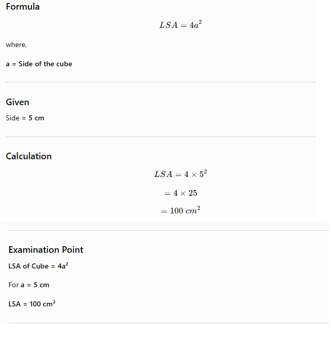
33. Lateral Surface Area (LSA) of a Cube
Definition
The Lateral Surface Area (LSA) of a cube is the total area of its four vertical faces, excluding the top and bottom faces.
34. Traceability in Calibration
Definition
Traceability is the property of a calibration process in which measurements are linked to an internationally or nationally recognized standard through an unbroken chain of documented comparisons, with the uncertainty of each comparison properly evaluated.
Importance
Traceability ensures:
- Accurate measurements.
- Reliable results.
- Standardization across laboratories.
- Compliance with quality standards.
- Quality assurance in measurement systems.
Features
A traceable calibration:
- Maintains an unbroken comparison chain.
- Uses recognized international standards.
- Documents every comparison.
- Includes measurement uncertainty.
Examination Point
Traceability = Calibration linked to internationally recognized standards.
35. Wave Set of Hacksaw Teeth
Definition
The Wave Set refers to the arrangement of hacksaw teeth in a slight wave pattern along the blade.This arrangement produces a kerf slightly wider than the blade thickness, thereby reducing friction and preventing blade jamming during cutting.
Pitch
The pitch is the distance between two consecutive teeth.For a wave-set hacksaw blade, the pitch is:0.8 mm
Importance
The wave set:
- Reduces friction.
- Prevents blade jamming.
- Produces smooth cutting.
- Improves cutting efficiency.
- Suitable for cutting thin materials.
Examination Point
Wave Set Pitch = 0.8 mm
36. Capacitive Proximity Sensor
Definition
A Capacitive Proximity Sensor detects objects by generating an electrostatic field.
Working Principle
The sensing face behaves like one plate of an open capacitor.When a target enters the electrostatic field:
- Capacitance changes.
- Internal oscillator detects the change.
- Output signal is generated.
Characteristic Feature
The operating principle is based on the generation of an electrostatic field.
Comparison with Other Sensors
| Sensor | Working Principle |
|---|---|
| Capacitive | Electrostatic Field |
| Inductive | Electromagnetic Field |
| Ultrasonic | High-frequency Sound Waves |
| Optical | Light Beam |
Examination Point
Capacitive Proximity Sensor → Electrostatic Field
37. Digital Frequency Counter
Definition
A Digital Frequency Counter measures the frequency of an electrical signal by counting the number of cycles occurring during a fixed gate time.
Limitation at Very High Frequencies
At very high frequencies, accurate counting becomes difficult because of:
- Finite gate time.
- Trigger limitations.
- Counting limitations.
- Time-base constraints.
Result
These limitations reduce:
- Measurement resolution.
- Measurement accuracy.
Examination Point
Disadvantage at high frequency → Reduced accuracy and resolution due to counting limitations.
38. IC 555 Timer – Comparators
Definition
The IC 555 Timer is a versatile integrated circuit used as a timer, oscillator, and pulse generator.Its internal block diagram contains:
- Voltage divider
- Two comparators
- Flip-flop
- Output stage
Comparator 1
Comparator 1 compares:
- Threshold Pin (Pin 6)
with
- 2/3 VCC
When the threshold voltage exceeds 2/3 VCC, the comparator changes the state of the flip-flop.
Comparator 2
Comparator 2 compares:
- Trigger Pin (Pin 2)
with
- 1/3 VCC
When the trigger voltage falls below 1/3 VCC, the flip-flop changes state.
Importance
The comparators determine the timing operation of the IC by controlling the flip-flop based on the threshold and trigger voltages.
Examination Point
IC 555 contains Two Comparators.
Quick Revision Table
| Topic | Important Fact |
|---|---|
| SCON Register | Controls Serial Communication |
| Darlington Pair | Very High Current Gain |
| Cube | LSA = 4a² |
| Traceability | Linked to International Standards |
| Hacksaw Blade | Wave Set Pitch = 0.8 mm |
| Capacitive Sensor | Electrostatic Field |
| Digital Frequency Counter | High frequency → Reduced Accuracy |
| IC 555 | Two Comparators |